• After 15+ years, we've made a big change: Android Forums is now Early Bird Club. Learn more here.

tundrafox1

Lurker
Dec 10, 2013
2
0
I designed and printed a charging cradle on a rapid prototyping printer at school, and I'm a little handy with solder, but I don't know which charge contact is which on the phone. Can Someone please take a multimeter to their charge cradle and inform me and other DIYer's of the polarity of each contact on the cradle (Positive/Neutral).
It would be greatly appreciated.
 
You cannot just solder the power supply pins of the USB charger to the terminals that connect to the phone. There is some sort of chip in there - at least I saw one when I chopped apart my charging cradle for my old 771 phone. (That old style charging cradle will charge the new 4G phones if you hack it with a dremel.) I'm guessing that chip is a current-limiting battery maintenance chip. If this is the case, you run the risk of overcharging or exploding your battery by connecting those terminals right to a power supply.
 
Upvote 0
If I have some time this weekend I'll try to see what that chip is, to see if it might be something that is easy to get a hold of.

What I would love is a charging clip... something that isn't a stand but snaps into place "hugging" the phone. There have been lots of times when I needed to charge the phone in the car and wished I had something I could just "clip and go".
 
Upvote 0
If you make a home made dock. Make sure its not more than 5V DV and 500 mAh. Since it depends on a simple pin connections and no protection circuits.

Isn't there a protection circuit built into the phone? I have a 2A (2000mA) charger I use both with and without a cradle. There is no external protection circuit when used without a cradle. The LED goes from red to blank when charging is complete with either method. :thinking:
 
Upvote 0
First off, the stock charger is a 5V, 850mah (0.85A). Yes, there is a charging protection circuit built in. I suppose the real question is the purpose of the chip in the dock, is it an rfid that turns on the dock connections in the phone, or just more mosfet?
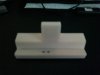
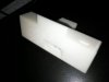
Attached are pics of the stand, yes it was printed with the access hole designed in. It also had pins on the dock, but i had to do some filing for the sake of fit. I modified the design in Solidworks, but without another iteration of prototyping, I cannot verify the revised fit.
I can upload the modified parts file for solidworks if anyone is interested. I cannot upload the new version .stl as the student version wont let me modify it (need to re-save on lab computers).
P.S. The design is small to fit inside a volume limit at the lab of 4 cu inches, it comes out to 3.99 cu in with support material on solid density.
 

Attachments

  • NCM_9551.JPG
    NCM_9551.JPG
    678.2 KB · Views: 144
  • NCM_9552.JPG
    NCM_9552.JPG
    463.9 KB · Views: 87
  • NCM_9553.JPG
    NCM_9553.JPG
    330.5 KB · Views: 97
Upvote 0
Measuring the terminals with a digital voltmeter gives no reading because the circuit needs to have a load in order to provide a charging current. I made a mod to the original cradle so I could use a mini-USB connector as well as the standard micro-USB. I soldered the positive and negative leads directly to the circuit board that supports the contacts bypassing the internal cradle circuit board. It seems to work just fine when supplied with a 5 VDC 850mA source.

I hope this helps.

C811-%20Cradle_Board.png


C811-%20Cradle_Mod.png
 
  • Like
Reactions: tundrafox1
Upvote 0

BEST TECH IN 2023

We've been tracking upcoming products and ranking the best tech since 2007. Thanks for trusting our opinion: we get rewarded through affiliate links that earn us a commission and we invite you to learn more about us.

Smartphones